Fundamentals of M-Bus
In the realm of industrial communication protocols, M-Bus (Meter-Bus) stands out as a prominent player. This European standard EN 13757-2 physical and link layer, and EN 13757-3 application layer, is designed for reading meter data from gas or electricity meters. It's a cost-effective, efficient, and reliable solution for data communication between various metering devices.
Understanding the M-Bus Protocol
The M-Bus protocol is a wired communication protocol that was initially designed for the remote reading of water, gas, or electricity meters. It has since been expanded to support various types of consumption meters and sensors. The primary advantage of M-Bus is its ability to collect data from a large number of devices over a single pair of wires, making it an ideal solution for large-scale industrial applications.

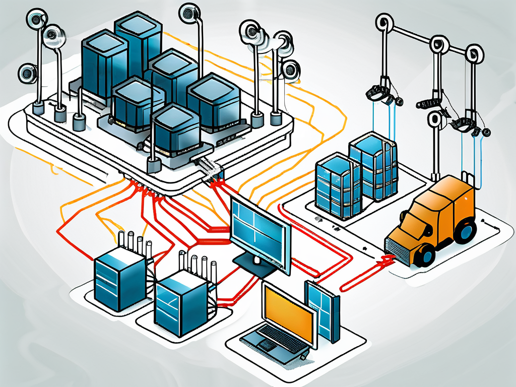
At its core, the M-Bus protocol operates on a master-slave topology. The master device, typically a central unit or a data logger, initiates communication and requests data from the slave devices, which are the meters or sensors. The slave devices respond to the master's requests but do not initiate communication.
Physical Layer of M-Bus
The physical layer of M-Bus is defined by the EN 13757-2 standard. It specifies the use of a two-wire bus for communication, with a maximum length of 1000 meters and a maximum of 250 connected devices. The data transmission rate is typically 300 baud, but higher rates up to 9600 baud can be used for shorter networks with fewer devices.
The physical layer also specifies the use of a voltage mode for communication. The master device sends out a voltage signal, and the slave devices respond by modulating the current. This method of communication is highly reliable and resistant to noise, making it suitable for industrial environments.
Link Layer and Application Layer of M-Bus
The link layer and application layer of M-Bus are defined by the EN 13757-3 standard. The link layer handles the addressing of devices and the error checking of data. Each device on the M-Bus network has a unique address, and the master device uses these addresses to communicate with the slave devices.
The application layer defines the data format and the types of data that can be transmitted. This includes consumption data, status information, and diagnostic data. The application layer also supports the encryption of data for secure communication.
Implementing M-Bus in Industrial Applications
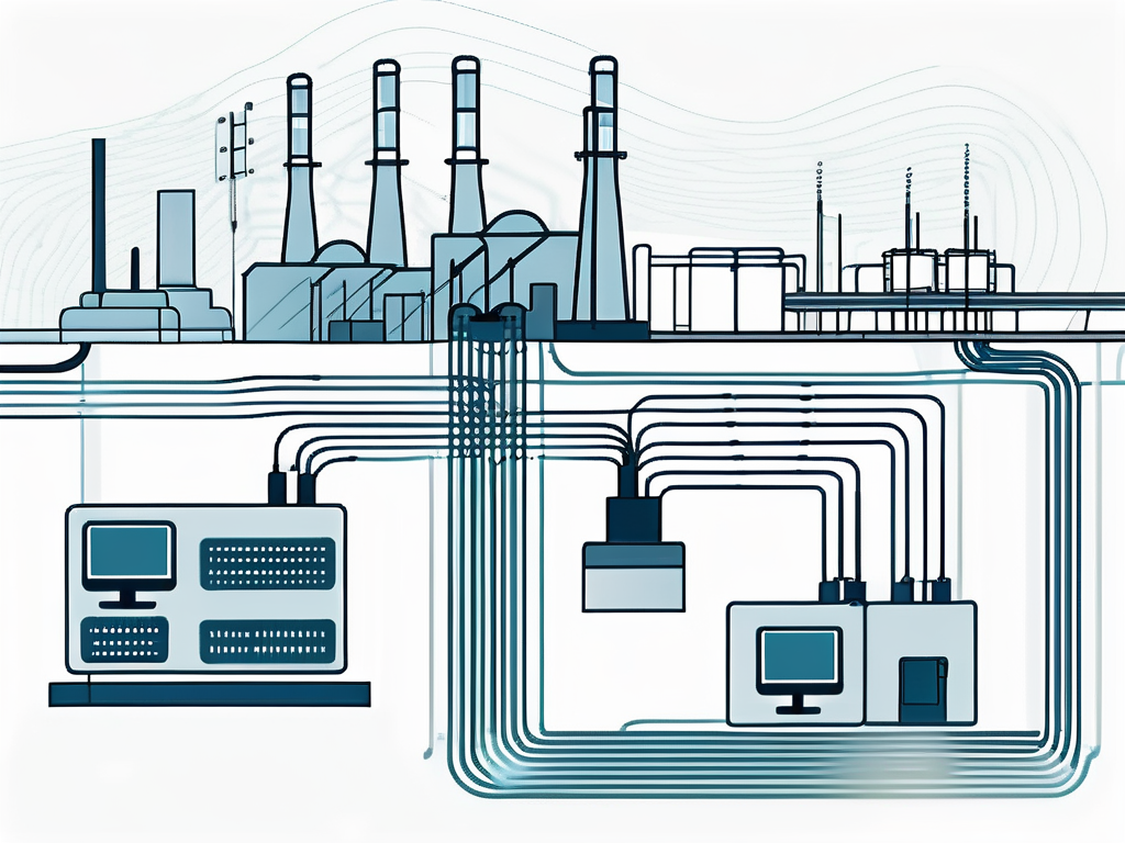
Implementing M-Bus in an industrial setting involves the installation of a wired network, the configuration of the master and slave devices, and the integration of the M-Bus data into the existing data management system.
The first step is to install the M-Bus network. This involves laying out the two-wire bus, connecting the devices, and setting up the power supply. The network should be designed to minimize the length of the bus and the number of connected devices to ensure reliable communication.
Configuring the Master and Slave Devices
The next step is to configure the master and slave devices. The master device needs to be set up with the addresses of the slave devices and the data request schedule. The slave devices need to be configured with their unique address and the type of data they will be transmitting.
Most M-Bus devices come with software tools for configuration. These tools allow you to set the device parameters, test the communication, and troubleshoot any issues. It's important to follow the manufacturer's instructions when configuring the devices to ensure proper operation.
Integrating M-Bus Data into the Data Management System
The final step is to integrate the M-Bus data into the existing data management system. This involves mapping the M-Bus data to the data model of the system and setting up the data import process.
The integration can be done using standard software tools or custom development, depending on the complexity of the system and the specific requirements of the application. The goal is to make the M-Bus data available for analysis and reporting, and to use it to optimize the operation of the industrial process.
Benefits of Using M-Bus in Industrial Applications
The use of M-Bus in industrial applications offers several benefits. First and foremost, it provides a reliable and efficient method for collecting data from a large number of devices. This can significantly reduce the time and effort required for data collection and increase the accuracy of the data.

Second, M-Bus supports a wide range of devices and data types, making it a flexible solution for various applications. Whether you need to monitor energy consumption, track production data, or measure environmental conditions, M-Bus can provide the necessary data.
Finally, M-Bus is a cost-effective solution. The hardware costs are relatively low, and the installation and maintenance are straightforward. This makes M-Bus a viable option for both small and large industrial applications.
Conclusion
In conclusion, M-Bus is a powerful tool for industrial data communication. Its robust design, flexibility, and cost-effectiveness make it an excellent choice for a wide range of applications. Whether you are a plant manager looking to optimize your operations, a system integrator designing a new system, or a product developer creating a new device, M-Bus can provide the data communication solution you need.


