|
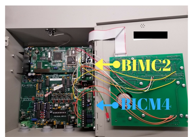
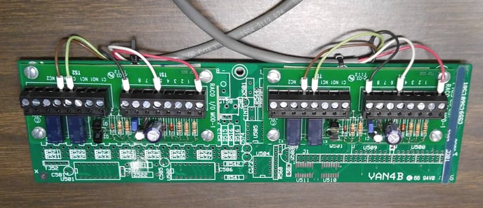
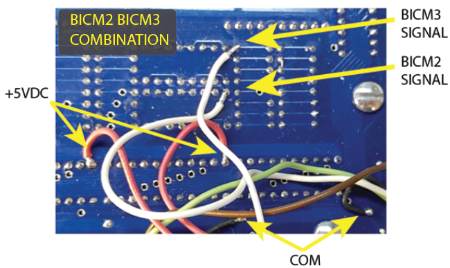
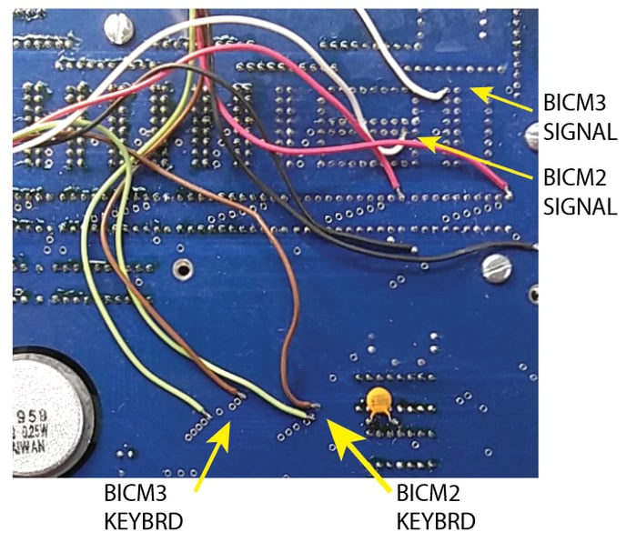
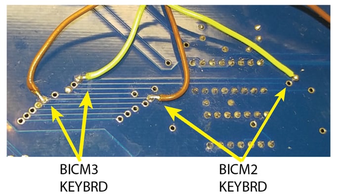
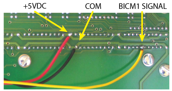
The BICM module provides remote control and indication of selected autodialer functions. The BICM is ordered configured in one of four standard configurations. The modules themselves are physically identical. The option number designation determines how it is configured and connected to match the specified functions. Some functions are controlled by jumpers and connections; others require factory changes. Other configurations may be available by special ordered.
Each module consist of two independent circuits. One provides a control function that allows an external signal to control some pre-configured functions in the autodialer. The second monitors pre-configured states of the autodialer and provides an output signal to an external circuit.
BICM Control Functions:
The BICM allows some preselected functions of the autodialer to be controlled by an external dry contact or 5VDC signal. The control function is determined by the option number and is pre-configured at the factory. Other functions may be available by special order.
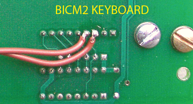
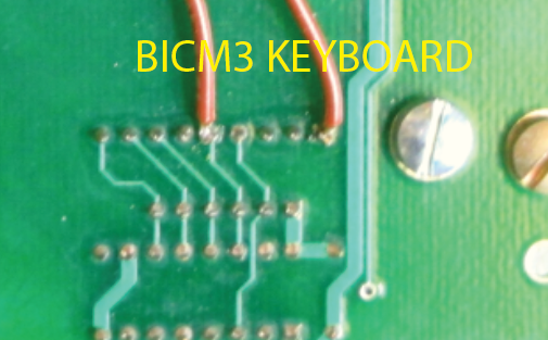
The control signal mimics a front panel keypress and operates exactly as if the corresponding function key has been pressed. Like a keypress, the control signal must be a momentary pulse. If the signal remains on, the autodialer acts like a key is stuck and may not function property. Most functions are toggles: e.g. one pulse will arm the autodialer and the next pulse will disarm it. The only way to know the specific state is to monitor the state with a different BICM channel.
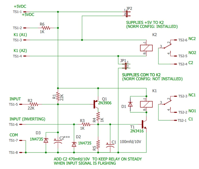
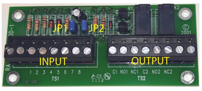
The control signal is connected to TS1-1 to TS1-4. The signal can be configured for a dry contact or a 5VDC signal by jumpers J1 and J2. It is typically a pushbutton, relay contact, or PLC output. The signal controls relay contacts C2, NO2, and NC2 on TS2. These contacts are wired at the factory to the internal circuits of the autodialed which controls its functions. Do not connect external circuits to these contacts.
All input signals are connected to TS1.
This is a functions description of the pins:
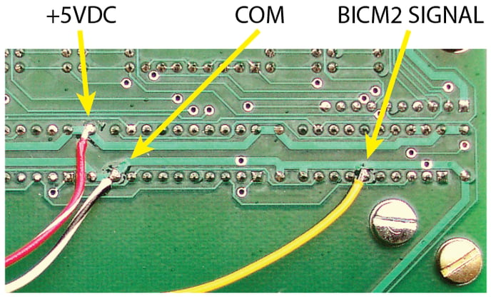
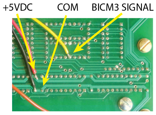
- 5VDC from the autodialer
- Pulled high by a 1K resistor to the 5VDC supply on pin 1
- Direct connection to the output relay's coil
- Direct connection to the other side of the output relays coil
- Normal Input - When 5VDC is applied the output relay is energized
- Inverting Input - When 0VDC is applied the output relay is energized
- Ground
- Ground
JB1 and JB2 are used to configure the inputs. JB1 connects one side of the output coil to ground (TS1-7 and TS1-8) JB2 connects the other side of the coil to 5VDC (TS1-1).
Dry Contact configuration: (JP1: INSTALLED, JP2: REMOVED) Connect a momentary, normally open, dry contact or switch between terminal TS1-4 and TS1-7. This will provide a ground to one side of the relay coil. JP2 supplies 5VDC to the other side.
Note: TS1-1 is connected to the autodialer's internal 5VDC power supply. If external voltage is applied or if the terminal is shorted it can damage the Verbatim Autodialer!
5VDC configuration: (JP1: REMOVED, JP2: REMOVED) Connect a 5VDC source to terminals TS1-3 and TS1-4. These two terminals connect directly to the relay coil. With JP1 and JP2 removed, the input wiring is isolated from the autodialer except for the relay coil. The relay requires approximately 30MA to operate. Do not apply more than 5VDC to the input or the relay may be damaged.
BICM Monitoring Functions:
The BICM can be connected to monitor most of the front panel indicators by selecting the specific option desired or by special order. An output relay contacts are provided to connect an alarm or PLC input. Monitoring signals from the autodialer are connected to TS1-5 and TS1-6 at the factory. TS1-5 is the Normal input. If the signal wire is connected here, the output relay is energized and contacts C2 and NO2 close when the front panel indicator is on. If the signal wire is connected to TS1-6, the signal is inverted so that the relay is energized when the indicator is off. The relay is always de-energized when the power is off.
A capacitor delay-off circuit keeps the relay energized when the indicator is flashing and for a few seconds after it turns off. This provides a steady signal to trigger the external circuit and prevents fast-cycling of the device.
Figure 1 Output Relay Contact Ratings

Typical Configuration:
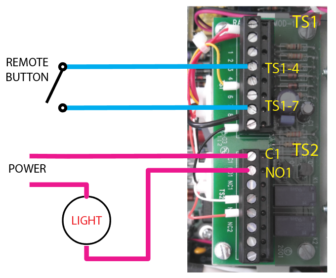
For a typical configuration, JP2 is installed which supplies +5vdc to one side of K2. JP1 is removed which isolates the other side of K2's coin. An external dry contact relay is connected between TS1-4 and COM (TS1-7 or TS1-8). When the external contact closes, it supplies and CON return for K2 which energizes it. Its contacts activate the configured function. K1 provides C(common), NO, and NC dry contacts on TS2-1, TS2-2, and2 TS2-3 respectively. The customer can connect their monitoring equipment here.
Wiring Example:
|
 next to the title to expand that section.
 Introduction
 Field Installation
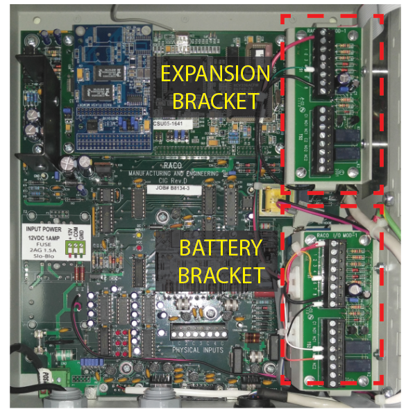
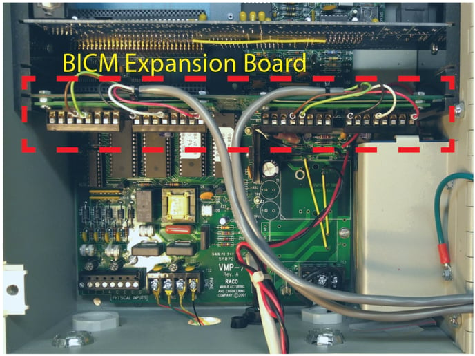
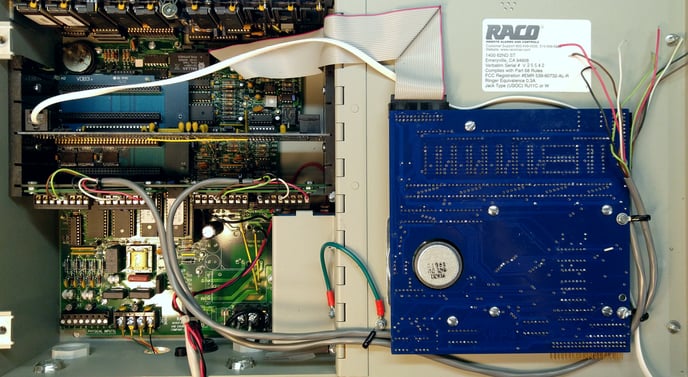
 Mounting Options


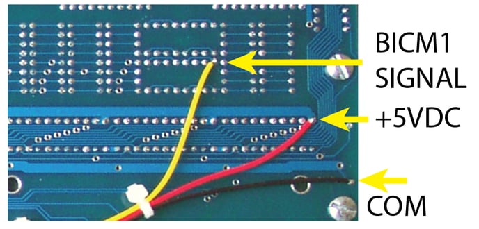
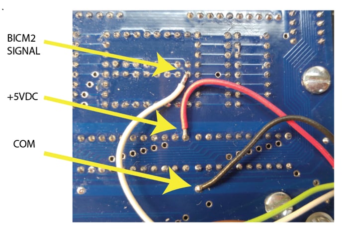

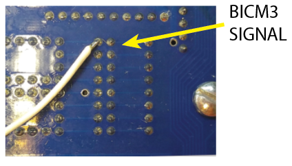

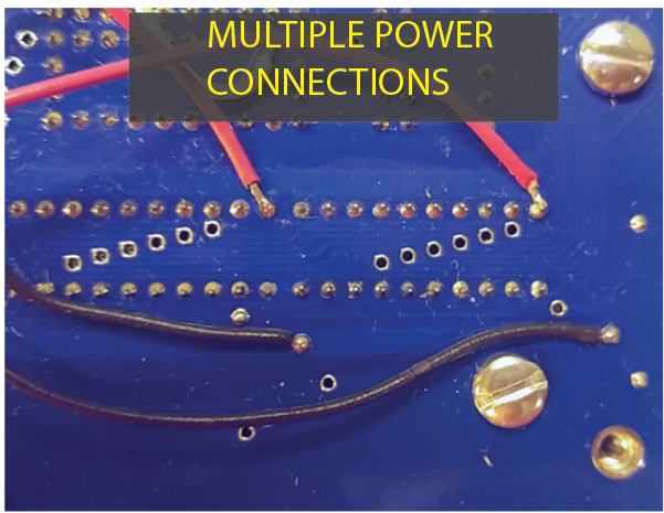
-jpg.jpeg)
